Home Improvement:


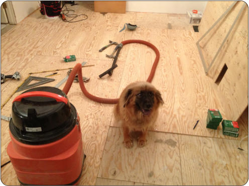
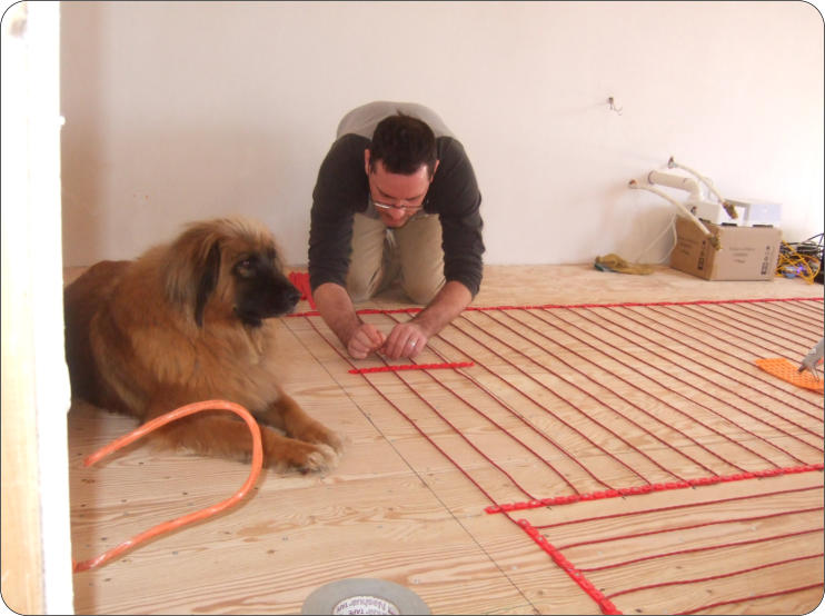
The tile substrate starts with a layer of 3/8” plywood
underlayment screwed to the top of the 3/4”
plywood subfloor. There are a ridiculous number of
screws - running every 8” in the plywood with 6” at
the underlayment edges. As usual, Ruby is helping.
NuHeat Warm Floor
Cabling
Warm Tootsies!
One of the many unplanned detours on the project
was the last minute decision to put in electric
heating elements in the thinset below the tile floor.
Although I’m a fan of radiant heating where the
building surfaces radiate heat rather than heating
the air, this was really just to take the edge off winter
mornings on bare feet.

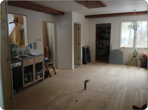
After finishing underlayment, each cabinet is
marked in permanent marker so that the electric
cable can be planned without needlessly heating
underneath cabinets or a refrigerator.

Note how the grid goes to where the toekick will
wind up in the cabinet, but not under the cabinet
itself. The guides have pegs that are pitched at
every inch. So we used a 3” pitch for most of this
floor..
The last bit is finished, but then we found out that
the floor was not at all flat. There was a distinct
ridge in the plywood centered around a basement
lally column. We hadn’t discovered this until the
thinset part was all done. It looked flat, but a 6 foot
straightedge showed that we’d after flatten the floor.
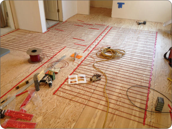
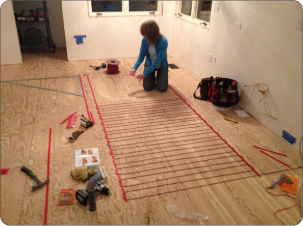
Here, you can see the spool of electric cable that is
run back and forth between the guides. Off the right
side of the picture is the black lead that goes up into
the wall to the floor heating thermostat.
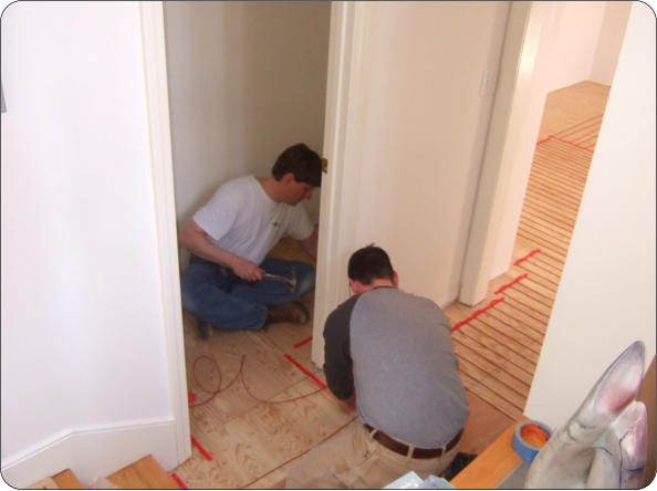
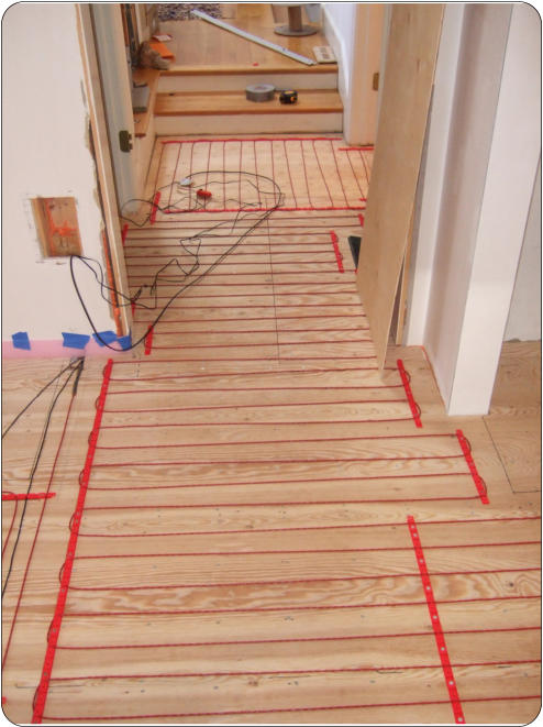
We had enough cable to continue down the hall and
into the hallway half bath. Since you can’t (or are
not supposed to) trim and rejoin the cable, it is
handy to have an area where you can run the cable
long
The finished cable grid is shown below. This was a relatively straightforward process. There is a more popular
option to go with pre-wired thin mats that are thinset-ed into place onto the underlayment. this is both easier and
less expensive for a regular layout like a simple combination of rectangles. However, each rectangle has its own
leads and all of them have to be make it back to a (big) splice at the thermostat. I didn’t like the idea of 5 thick
cables coming up through the wall and the pair of 5-wire splices, so instead I ordered the long cable / guides, and
ran it in the pattern below. The cable has a dead-end at the far side, and the cable actually has both electrical
wires inside so that so that the circuit is formed. Obviously, there is no ability to field-trim the cable
The manufacturer (NuHeat, in this case) supplies
cable guides that can be easily cut and tacked into
place so that the electric grid of cables stays neat
until embedded in thinset mortar
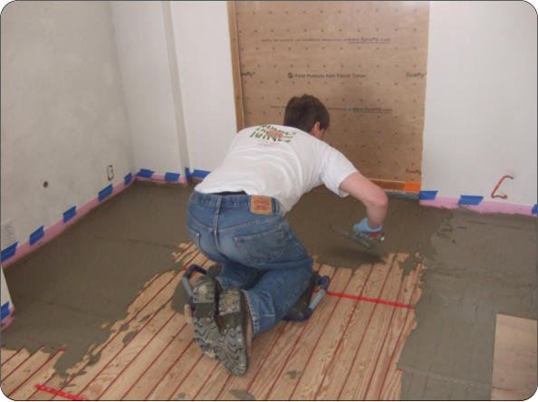
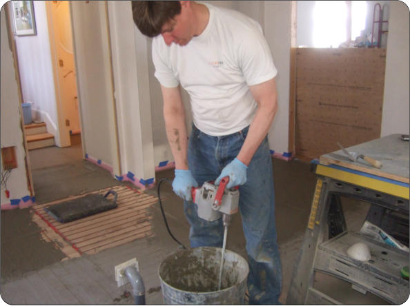
After running the cable and before somebody
breaks it from walking on it, the cable is covered in
either thinset or Self Leveling Compound. We
chose Laticrete 254 latex modified thinset.
Incredibly smooth, sticky, and hard when cured.
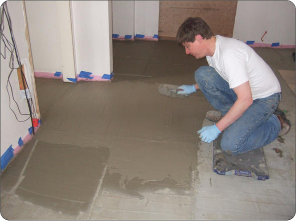
Another batch of Laticrete being mixed and troweled
over the wires.
II had a couple of helpers on this one - That’s Ruby
and Joe above